Deep Hardness 2.0
Description:
Deep Hardness 2.0 calculates the safety factors ηi related to the contact fatigue examination as a function of the surface depth, on assuming discontinuities like not metallic inclusions as nucleation sources for subsurface fatigue cracks, according to the Murakami-Endo theory. Deep Hardness 2.0 uses the Hertz theory for the calculation of the contact pressure, then it is valid for cylindrical bodies (absence of convexities). The core resistance is inspected according to the Von Mises criteria.
In case of coupling of materials with different Poisson coefficient, the examination in calculated referred to the body with subscript 2.
Conditions:
- The tool does not consider the chemical nature of the inclusion (sulphide or oxide), its degree of adhesion to the metallic matrix and the distribution inside it. The presetted maximum dimension d relative to the bigger inclusion, equal to 50 µm, is considered properly precautionary with respect to the manufacturing methodologies of the modern special structural steels destined to the realization of components subjected to contact fatigue (steels for surface hardening, quench and tempering steels, carburizing steels, nitriding steels with the exception of the RE-SULPHURIZED and ADDED-Pb types ). To obtaining a further refining of the calculation it is suggested to follow the DH1 procedure for the determination of d defined in Deep Hardness 1.0 (contact fatigue measuring). Only in the case of use of specific steels for bearings it is advised to put d=30 µm avoiding to perform the inquiry defined by the DH1 procedure.
- It is not considered the micro structural variation that is highlighted from the core surface consequent to the specific surface hardness treatment (for example white layers during nitriding, retained austenite during carbonitriding)
- Convexities are not considered
Usefulness:
- Optimization of the surface hardness treatment
- Backing for calculations to the metallurgical failure analysis
Caution:
- Deep Hardness 2.0 requires the introduction of a micro hardness gradient HV1 according to the zi depth calculated and presetted. In any case it is possible to change the steps with the aim to favour the measurement. This gradient must be obtained from a normal section to the body contact surface, after suitable mounting and grinding, in the point that we are checking. For z=0 introduce the HV1 surface hardness. For planar cams and bearing races it must be considered, along the whole profile, the heaviest condition in terms of F, D1 and D2
- For a further refining of the inspection it is necessary to evaluate the micro purity of the steel determining the value d in µm of the maximum dimension d of the bigger not metallic inclusion. For that aim follow the DH1 procedure defined in Deep Hardness 1.0 (contact fatigue measuring).
Use:
- Introduce the required parameters in the entry mask
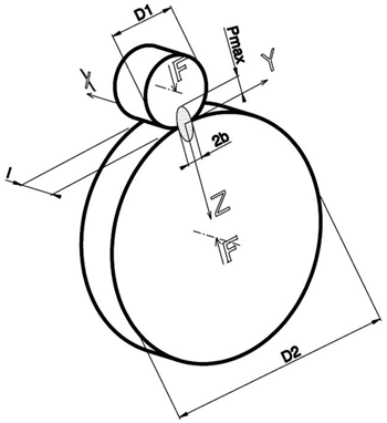
- D1 and D2 : diameters of the osculating circles of the bodies in the contact point respecting the convention of signs of the Hertz theory. For internal surfaces, the diameter is negative. For the cogwheels these diameters are calculated by the suitable routine putting in the number of frips, the modulus, pressure angle and helix angle of the gear. It is considered the pitch contact point between the frips.
- F : contact force between the bodies
For the cogwheels the strength is calculated introducing the couple that acts on the pinion (wheel 1), besides the dates indispensable to calculate D1 e D2. It is necessary to introduce even the overloading factor (K), utilised in the measuring of the gear, obtained as a product of the overloading factors relative to each contribution, that is: application load factor (Ka), dynamical factor (Kv), longitudinal distribution of the load factor (Khβ), transversal distribution of the load factor (Khα), according to UNI 8862-1/2:1987 - l : contact width, that is band width of the cam or rolling race.
For the cogwheels it is calculated putting in the width b of the gear (it is always intended the overlap width) - E1 ; E2 ; ν1 ; ν2 : haracteristics of the material of the bodies in contact: Young modulus, Poisson coefficients of the bodies 1 e 2
- η : safety factor towards the yielding due to contact fatigue
- μ : friction coefficient between the bodies in contact
- d : maximum dimension of the bigger not metallic inclusion
- Start the calculation
- The first results is the indication of the measurement steps zi. This indication is only for guidance. It is possible to change the steps, as long as we stay in the min and max limits suggested, to favour the measurement. For example for a suggested step zi=1,21 mm, it is absolutely allowed to put zi=1,20 mm
- Introduce the HV1 values correspondent to the zi chosen
- Complete the examination
- Check the safety factors ηi. We have got failure for ηi<=1
